Content Map
Process Heaters, Boilers and Furnaces
3.11.2 Process heaters, boilers and furnaces
J. M. Rhine, J. S. Truelove
A. Process heaters
Process heaters are used in the refinery and petrochemical industry to heat hydrocarbon feedstocks for fractionation, thermal cracking and high-temperature processing. The feedstock, or process fluid, flows through tubes within the heater and must receive a specified amount of heat, without local overheating of the fluid or structural components. For these applications process heaters fall into two main categories, namely conventional process heaters and chemical reaction furnaces. Conventional process heaters are used to preheat hydrocarbon fluids, or occasionally other compounds, for subsequent processing in other unit operations. Chemical reaction furnaces are used where a chemical process is carried out inside the furnace tubes. Operating temperatures within the tubes may be as high as 900 °C, and at a pressures of 20,000 kPa. Process heater size is defined in terms of its design heat absorption, or duty. The majority of units fall within the range of 3 to 100 MW, although very large steam hydrocarbon reformers may run to 300 MW or more. Oil and gaseous fuels are used exclusively in these heater but the fuels will often be derived from waste streams from the refinery or petrochemical processes. Hence they can have unusual compositions and often vary in composition with time.
The main differences between chemical reaction furnaces and conventional process heaters lies in the degree to which the economics dictate how the heat flux to the process tubes should be controlled. For chemical reaction furnaces, throughput maximisation requires that the heat flux should be uniformly close to the maximum allowable over as large a tube area as possible. This usually results in specialised designs with large numbers of burners, often transferring the heat from radiating walls to the process tube outside surface area. In conventional heaters there is less economic incentive to approach the maximum allowable heat flux so closely. Thus simpler furnaces are employed with fewer burners. This gives a less uniform heat flux distribution and, usually, the heat is transferred predominantly to one side of the furnace tubes that line the inside walls of the heater enclosure.
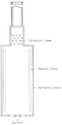
Thus, there are many variations in the layout, design and detailed construction of process heaters Berman (1978), Evans (1974), Baukel (2001). A typical conventional process heater arrangement is shown in Figure 1. It consists of a bottom-fired vertical cylindrical furnace chamber, also known as the firebox or radiant section, within which the fuel is burned. The walls, roof, and floor of the chamber are generally constructed from refractory material. The chamber contains heat-absorbing tubes arranged vertically along the walls, which remove a part of the heat from the flame gases before they flow to the convection section. The temperature of the combustion product flue gases leaving the radiant section is typically between 700 and 1,000 °C, and is commonly termed the bridgewall temperature. The convection section tubes are arranged as a horizontal bank of tubes positioned above the combustion chamber, and they recover additional heat from the furnace gases at a lower temperature level than that for the radiant section tubes. In this section the principal model of heat transfer is convection. Fins and other types of extended surface are frequently used to enhance the heat transfer. However, the first row or two of tubes in the convection section, known as shock or shield tubes, also receive significant heat by radiation from the radiant section. Extended surfaces cannot be used on the shock tubes because of the severe effect of radiation on the extremities of the surface extensions.
... You need a subscriptionOpen in a new tab. to view the full text of the article. If you already have the subscription, please login here