Content Map
Typical Configurations of Twisted Tube Heat Exchangers
DOI 10.1615/hedhme.a.000386
3.23.1 Typical configurations of twisted tube heat exchangers
Boris V. Dzyubenko, Guenrikh A. Dreitser
A. Heat exchanger with twisted tubes in longitudinal flow
(a) Typical twisted tube heat exchanger
In a typical twisted tube heal exchanger, a straight bundle of oval-shaped twisted tubes is used with the tubes being located relative to each other such that they have contact at the maximum points of the oval. The tubes have straight round ends which are fastened into the tube plates Dzyubenko (1980). Such a tube arrangement provides substantial enhancement of the heat and mass transfer processes in the intertube space of the heat exchanger and also reduces the propensity for tube vibration (Figure 1).
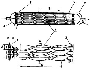
In twisted tube heat exchangers, all the tubes are twisted in one direction (either left, or right). In this case, at the boundary of the spiral channels between the tubes there appear tangential discontinuities of the rotational velocity component, resulting in flow turbulization. Heat transfer enhancement in the intertube space and inside the twisted tubes at optimum relative twisting pitches (s/d = 6 - 15, where s is the twist pitch - see Figure 1 - and d is the maximum size of the tube oval profile) enables one to decrease the heat exchanger volume by 1.5 - 2 times, as compared to a smooth-tube heat exchanger at prescribed thermal duty and pumping power for the fluid. In this case, the mass of the heat exchangers and the utilisation of construction materials also decrease.
... You need a subscriptionOpen in a new tab. to view the full text of the article. If you already have the subscription, please login here