Navigation by alphabet

A B C D E F G H I J K L M N O P Q R S T U V W X Y Z
Ideal gas: Ilexan, heat transfer medium, Illingworth, A, Imbedded fins, Immersed bodies: Immersed tubes, in fluidized beds, heat transfer to, Immiscible liquids, condensation of vapors producing Impairment of heat transfer in combined free and forced convection in a vertical pipe, Imperfectly diffuse surfaces: Impingement damage in heat exchangers, Impingement plate: Impingement protection, in shell-and-tube heat exchangers, Impinging jets: Implicit equations, solution of Inclined enclosures, free convective heat transfer in, Inclined flow, effect of on heat transfer to cylinders, Inclined pipes: Inclined surfaces, free convective heat transfer from, Inconel, spectral characteristics of reflectance from oxidized surface of, Induced flow instabilities, in augmentation of heat transfer, Injection: Inlet effects in shell-and-tube heat exchangers, In-line tube banks: Inorganic compounds, solutions of, as heat transfer media, Inorganic substances: Instability, parallel channel, in condensers, Insulators, thermal conductivity of, Integral condensation: Integral finned tubes: Interaction coefficients in heat exchangers, Interaction parameters for binary systems, tables, Interfacial friction, in three-phase (liquid-liquid-gas) stratified flows, Interfacial resistance, in condensation, Interfacial roughness, relationships for, in annular gas-liquid flow, Interfacial shear stress, effect on filmwise condensation, on vertical surface, Intergrannular corrosion, of Intermating troughs, as corrugation design in plate heat exchangers, Intermittent flows: Internal heat sources, temperature distribution in bodies with, Internal heat transfer coefficient, use in transient conduction calculations, Internal reboilers (in distillation columns), characteristics advantages and disadvantages of, Internally finned tubes: International codes for pressure vessels, Interpenetrating continua (as representation of heat exchangers): Intertube velocity, in tube banks, Inviscid flow, compressible, with heat addition, Iodine: Iodobenzene: Iodoethane: Iodomethane: ISO codes for mechanical design of heat exchangers, Isobutane: Isobutanol: Isobutylamine: Isobutylformate: Isobutyric acid: Isoparaffins: Isopentane: Isopentanol: Isopropanol: Isopropylacetate: Isopropylamine: Isopropylbenzene: Isopropylcyclohexane: Isothermal flow, compressible, in ducts, Isothermal gas, radiation heat transfer to walls from, Isotropic materials, elastic properties, Isotropic scattering, Italy, guide to national practice for heat exchanger mechanical design,

Index

HEDH
A B C D E F G H I
Ideal gas: Ilexan, heat transfer medium, Illingworth, A, Imbedded fins, Immersed bodies: Immersed tubes, in fluidized beds, heat transfer to, Immiscible liquids, condensation of vapors producing Impairment of heat transfer in combined free and forced convection in a vertical pipe, Imperfectly diffuse surfaces: Impingement damage in heat exchangers, Impingement plate: Impingement protection, in shell-and-tube heat exchangers, Impinging jets: Implicit equations, solution of Inclined enclosures, free convective heat transfer in, Inclined flow, effect of on heat transfer to cylinders, Inclined pipes: Inclined surfaces, free convective heat transfer from, Inconel, spectral characteristics of reflectance from oxidized surface of, Induced flow instabilities, in augmentation of heat transfer, Injection: Inlet effects in shell-and-tube heat exchangers, In-line tube banks: Inorganic compounds, solutions of, as heat transfer media, Inorganic substances: Instability, parallel channel, in condensers, Insulators, thermal conductivity of, Integral condensation: Integral finned tubes: Interaction coefficients in heat exchangers, Interaction parameters for binary systems, tables, Interfacial friction, in three-phase (liquid-liquid-gas) stratified flows, Interfacial resistance, in condensation, Interfacial roughness, relationships for, in annular gas-liquid flow, Interfacial shear stress, effect on filmwise condensation, on vertical surface, Intergrannular corrosion, of Intermating troughs, as corrugation design in plate heat exchangers, Intermittent flows: Internal heat sources, temperature distribution in bodies with, Internal heat transfer coefficient, use in transient conduction calculations, Internal reboilers (in distillation columns), characteristics advantages and disadvantages of, Internally finned tubes: International codes for pressure vessels, Interpenetrating continua (as representation of heat exchangers): Intertube velocity, in tube banks, Inviscid flow, compressible, with heat addition, Iodine: Iodobenzene: Iodoethane: Iodomethane: ISO codes for mechanical design of heat exchangers, Isobutane: Isobutanol: Isobutylamine: Isobutylformate: Isobutyric acid: Isoparaffins: Isopentane: Isopentanol: Isopropanol: Isopropylacetate: Isopropylamine: Isopropylbenzene: Isopropylcyclohexane: Isothermal flow, compressible, in ducts, Isothermal gas, radiation heat transfer to walls from, Isotropic materials, elastic properties, Isotropic scattering, Italy, guide to national practice for heat exchanger mechanical design,
J K L M N O P Q R S T U V W X Y Z

Impinging Jets

DOI 10.1615/hedhme.a.000173

2.5.6 Impinging Jets

A. Introduction

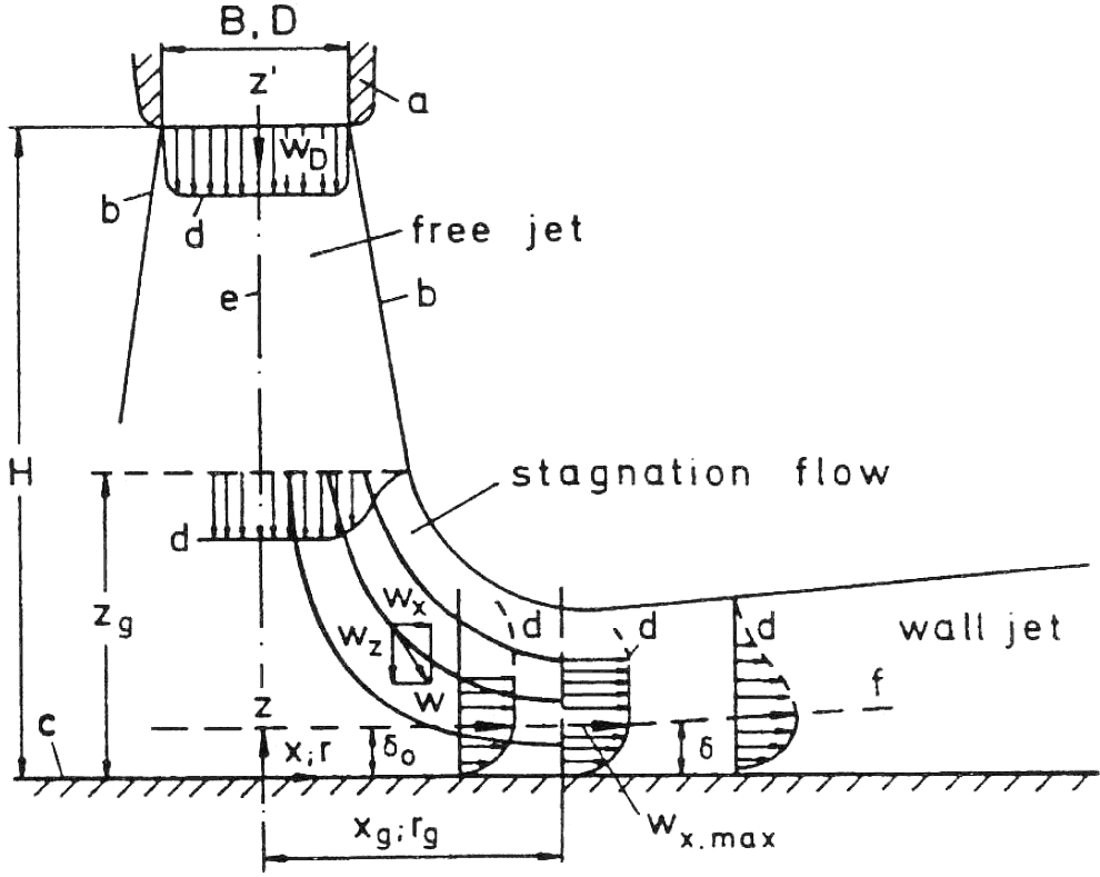
Heating or cooling of large-surface-area products is often carried out by means of arrays of round or slot nozzles. A fluid (typically, air) impinges upon the product surface. Impinging flow devices allow short flow paths to the surface small boundary layers and, therefore, relatively high heat and mass transfer rates. For these reasons impinging jets are used in the fields of paper drying, the drying of functional films, thin film coating applications (such as optical foils), battery electrodes, and many other industrial applications. The fluid temperature, fluid flow rate, diameter (or slot width) of the impingement nozzles, distance to the surface, and spacing and alignment between the nozzles are the main variables, which can be adjusted for a given heat or mass transfer problem. As shown by Schrader (1961), Glaser (1962 and 1963), and other authors (Lohe, 1967; Petzold, 1968; Kumada and Mabuchi, 1970; Romanenko and Davidzon, 1970), the flow pattern of impinging jets from single round and slot nozzles can be subdivided into three characteristic regions: the free jet region, the stagnation flow region, and the region of lateral (or radial) flow outside the stagnation zone, also called the wall jet region after the basic theoretical work of Glauert (1956). The velocity field of an impinging jet is shown schematically in Figure 1. The free jet, at the exit of the nozzle, a, with diameter D or slot width B, in general will be turbulent (for typical industrial application conditions). By intensive exchanger of momentum with the surrounding gas over the free boundaries, b, the jet broadens linearly with its length, z', up to a limiting distance, zg, from the solid surface, c. The velocity profile, d, being nearly rectangular at the nozzle exit, spreads toward the free boundaries and, for sufficient length of the free jet, approaches a bell shape. Toward a substrate, stagnation flow begins relatively close to the surface [ according to Schrader (1961), limiting distance zg is about 1.2 times the nozzle diameter ]. Here, the vertical velocity component is decelerated and transformed into an accelerated horizontal one. Analytical solutions of the Navier–Stokes equations are known for the idealized limiting case of the infinitely extended plane and axisymmetric laminar stagnation flows [ see Schlichting (1958), pp. 76–81 ]. Because of the finite range of the jet and the exchange or momentum with its motionless surroundings, the accelerated stagnation flow finally must transform to a decelerated wall jet flow. Thus, the wall parallel velocity component wg (wr), initially increasing linearly from zero, must reach a maximum value at a certain distance xg (rg) from the stagnation point, and finally tends to zero with xn (rn) in the fully developed wall jet. Exponent n is about −0.5 for the plane (Glauert, 1956; Seban and Back, 1961; Schwartz and Cosart, 1961) and about −1 for the axisymmetric (Glauert, 1956; Seban and Back, 1961; Bakke, 1957) turbulent wall jet. While the stabilizing effect of acceleration keeps the boundary layer laminar in the stagnation zone, transition to turbulence generally will occur immediately after xg (or rg) in the decelerating flow region. The wall boundary layer and free jet boundary grow together, forming the typical wall jet profile where the boundary layer, σ, is defined as the locus of the maxima of the velocity [ z(wx,max) ] (see f in Figure 1). In principle, the impinging flow from arrays of nozzles shows the same three flow regions: free jet, stagnation zone, and wall jet. However, in addition to that, secondary stagnation zones occur where the wall jets of neighboring nozzles impinge upon each other. These secondary stagnation zones are characterized by boundary layer separation and eddying of the flow at the substrate position where the neighboring jets interact.

Figure 1 Velocity field of impinging flow

B. Local Heat and Mass Transfer Coefficients

(a) Single Round Nozzles (SRNs) and Single Slot Nozzles (SSNs)

... You need a subscriptionOpen in a new tab. to view the full text of the article. If you already have the subscription, please login here