Navigation by alphabet
A B C D E F G H I J K L M N O P Q R S T U V W X Y ZIndex
Utility Selection
DOI 10.1615/hedhme.a.000124
1.7.5 Utility Selection
B. Linnhoff, R. Smith
A. Introduction
So far we have considered utilities of constant temperature such as steam or essentially constant temperature such as cooling water. For utilities of non-constant temperature (e.g. flue gas, boiler feedwater preheat, etc.) targeting and design become more complex. In this chapter a new tool is discussed, the Grand Composite Curve Linnhoff (1982), Linnhoff (1986), Greenkorn et al. (1978), which is used for both utilities of constant and non-constant temperature. Flue gas, multiple steam levels, boiler feedwater, heat engines, heat pumps, etc., are included in what is a perfectly general procedure.
Consider the heat exchanger network shown in Figure 1 Linnhoff (1986). Figure 1 shows a process flowsheet. The design of the heat recovery system achieves its energy target of 300 units of externally supplied energy. The design provides this heat from a furnace.
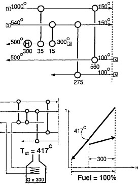
Figure 1 A heat exchanger network design which achieves the target. Because the hot utility is a furnace, the fuel required is greater than the heating duty
The designer would like to minimize the fuel consumption by extracting as much heat as possible from the flue gas. This means obtaining as low a temperature as possible in the stack. By lowering the stack temperature, the designer lowers the flowrate of flue gas and hence the quantity of fuel which must be burned. The lowest temperature the flue gas can be taken to is the acid dew point (160 °C in this case). Unfortunately, the furnace coil inlet temperature of 367 °C means that a high stack temperature of 417 °C is being achieved in Figure 1.
... You need a subscriptionOpen in a new tab. to view the full text of the article. If you already have the subscription, please login here