Content Map
Numerical examples
DOI 10.1615/hedhme.a.000110
1.6 SHELL-AND-TUBE HEAT EXCHANGERS (CELL METHOD)
1.6.3 Numerical examples
E.S. Gaddis
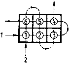
A shell-and-tube heat exchanger has two tube-side passes and two segmental baffles (i.e. three shell-side passes). The flow configuration of the idealized heat exchanger is shown in Figure 1; both heat exchanger nozzles are located in the same cell. It is required to calculate the effectiveness of the heat exchanger and to calculate the outlet temperatures of both fluids. The following data are given:
- Mass flow rate Ṁ1 = Ṁ2 = 0.0834 kg/s
- Specific heat capacity c1 = c2 = 103 J/kg K
- Inlet temperature of cold fluid = 10 °C
- Inlet temperature of hot fluid = 60 °C
- Cell effectiveness Ec = 0.4
It is assumed that Ec is constant in all cells; a calculation of the value of Ec is carried out in the example in Section 117.
Calculations:
... You need a subscriptionOpen in a new tab. to view the full text of the article. If you already have the subscription, please login here