Content Map
Special case of two tubes passes
DOI 10.1615/hedhme.a.000112
1.6 SHELL-AND-TUBE HEAT EXCHANGERS (CELL METHOD)
1.6.5 Special case of two tube-side passes
E.S. Gaddis
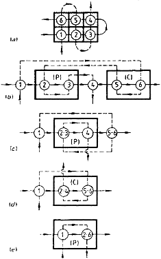
The special case of two tube-side passes has a simple flow configuration, which enables a quick calculation of the heat exchanger effectiveness (Gaddis and Vogelpohl, 1984). The computation procedure is described by an example. Consider the heat exchanger treated in Section 110 with geometry G.1. This heat exchanger is illustrated once more in Figure 1a, while Figure 1b is intended to clarify the type of connection between the cells. It is seen in Figure 1b that parallel flow (P) exists between cells 2, 3, and 4 and counter flow (C) between cells 5 and 6.
The effectiveness of a heat exchanger composed of two units coupled in parallel flow or in counter flow may be evaluated from the following equations (VDI, 1977).
For parallel flow:
\[\label{eq1} E = E_{u,1}+ E_{u,2}-(1 + R)E_{u,1} E_{u,2} \tag{1}\]
... You need a subscriptionOpen in a new tab. to view the full text of the article. If you already have the subscription, please login here