Content Map
Special case of three tube-side passes and two-segmental baffles
DOI 10.1615/hedhme.a.000115
1.6 SHELL-AND-TUBE HEAT EXCHANGERS (CELL METHOD)
1.6.8 Special case of three tube-side passes and two segmental baffles
E.S. Gaddis
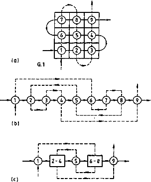
Two of the four possible geometries G.1 to G.4 of a heat exchanger with three tube-side passes and two segmental baffles (three shell-side passes) have flow configurations, which enable a quick calculation of the heat exchanger effectiveness by the procedure described in Section 112. These are the geometries G.1 and G.4 with the lowest and the highest heat exchanger effectiveness respectively. The steps of the computations are demonstrated with an example for the case, when the ratio of the heat capacity rates R = 1 and the cell effectiveness Ec = 0.3.
A. Heat exchangers with geometry G.1
The steps of calculations are clear from Figure 1.
\[E_{p,2 \to 3} = 0.3 + 0.3 - 2\times 0.3\times 0.3 = 0.420\] (parallel flow)
... You need a subscriptionOpen in a new tab. to view the full text of the article. If you already have the subscription, please login here