Content Map
Heat exchangers with longitudinal baffles
DOI 10.1615/hedhme.a.000116
1.6 SHELL-AND-TUBE HEAT EXCHANGERS (CELL METHOD)
1.6.9 Heat exchangers with longitudinal baffles
E.S. Gaddis
A shell-and-tube heat exchanger with a longitudinal baffle, as illustrated schematically in Figure 1a, may be treated as two units coupled in a parallel flow or in a counter flow.
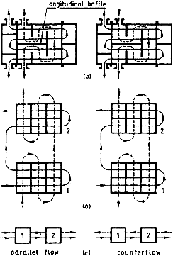
Figure 1 A shell-and-tube heat exchanger with a longitudinal baffle; shell-side nozzles are located near the tube side nozzles
Example: The heat exchanger in Figure 1a has from each side of the longitudinal baffle two tube-side passes and two segmental baffles. it is required to calculate the heat exchanger effectiveness given the following data:
Cell effective Ec = 0.4
Ratio of heat capacity rates R = 1
The calculations are as follows.
... You need a subscriptionOpen in a new tab. to view the full text of the article. If you already have the subscription, please login here