Content Map
Introduction
DOI 10.1615/hedhme.a.015655
3.1.2 TYPES OF HEAT EXCHANGERS
3.1.2D Shell-and-tube heat exchangers
Kenneth J. Bell
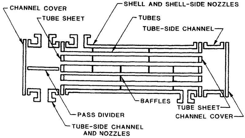
A typical shell-and-tube exchanger is shown in Figure 1. In their various construction modifications, they are, undoubtedly, the most commonly used basic heat exchanger configuration in the process industries. The particular design shown has one shell-side pass and two tube-side passes, i.e., the tube-side fluid flows through half of the tubes and then turns around in the rear tube-side channel and flows back to the front tube-side channel. Any number of tube-side passes can be achieved by suitable placement of pass dividers in the tube-side channels, but usually an even number is chosen. Single pass design is obtained by eliminating the pass divider and putting one tube-side nozzle on each channel.
The shell-and-tube heat exchanger provides fairly high ratios of heat transfer area to volume and weight. It provides this surface in a form that is relatively easy to construct in a wide range of sizes and that is mechanically rugged enough to withstand normal shop fabrication stresses, shipping and field erection, and external and internal stresses encountered under normal operating and maintenance conditions. The shell-and-tube exchanger can be cleaned reasonably easily, and those components most subject to failure - gaskets and tubes - can be easily replaced in most designs. Special construction features allow this type to meet al.most any conceivable service, including extremely low and high temperatures and pressures, large temperature differentials, vaporizing and condensing services, and severely fouling and corrosive fluids. Good design methods are available, and the expertise and shop facilities for their successful design and construction are widespread. Section 68 describes in considerable detail the mechanical features of shell-and-tube exchangers, Section 43 the design methods for sensible heat transfer service on the shell side, Section 44 the methods for condensation on the shell side, and Section 45 and Section 46 the use and design of shell-and-tube exchangers for vaporizing and evaporation services.
The tubes are the basic component, providing the heat transfer surface between one fluid flowing inside the tubes and the other fluid flowing across the tubes. The tubes may be either plain or with low fins on the outside to increase the ratio Ao / Ai; in this case the fin outside diameter is slightly less than the outside diameter of the unfinned ends of the tube to allow the tubes to be inserted through the holes in the tube sheets. Many types of other performance-enhanced tubes are available with enhancements on both the inside and the outside surfaces; these include spiral fluting, ribbing, twisted wire and tape inserts, and special surface treatments and configurations to improve vaporization and condensation. The tubes are held in place by the tube-sheets at each end (except the U-tube design, which has only one tubesheet). The tubes are either expanded into radial grooves cut into the tubesheet holes or welded to the tubesheet. In some low-pressure applications, the tubes are simply expanded into ungrooved holes in the tubesheets.
The tubesheet is a circular metal plate that has been suitably drilled and grooved for the tubes, milled to accommodate the pass divider gaskets, tapped for the tie rods, and drilled for the bolt circle (if the tubesheet is bolted to the shell flange; the tubesheet may also be welded to the shell).
... You need a subscriptionOpen in a new tab. to view the full text of the article. If you already have the subscription, please login here