Content Map
Coil Wound Heat Exchangers
DOI 10.1615/hedhme.a.015672
CRYOGENIC HEAT EXCHANGERS
Coil wound heat exchangers
G. Venkatarathnam
The coil wound heat exchanger was invented nearly a hundred years ago for use in large-scale liquefaction of air. The history of air separation is, in fact, intertwined with that of the coil wound heat exchangers (Aithal et al., 1988). Both Linde and Hampson used coil wound heat exchangers, but of different designs. While Linde used a coiled tube-in-tube heat exchanger, Hampson’s design consisted of a number of tubes wound helically over a mandrel and placed inside a shell as shown in Figure 1. The design was further improved by Giaque, who placed punched brass strips to help in uniform spacing of tubes within any layer (Barron, 1985). Coil wound heat exchangers are also popularly known as Giaque–Hampson heat exchangers, spiral tube heat exchangers,1 or coiled tubular heat exchangers, and are used extensively in natural gas liquefaction processes.
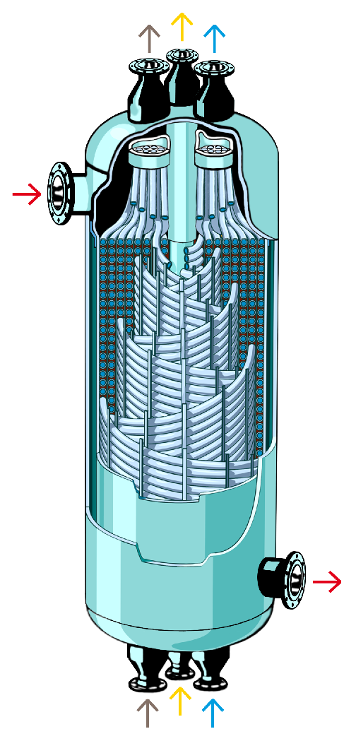
Figure 1 Coil wound heat exchanger (reproduced with permission from Linde AG Engineering Division, Germany)
The coil wound heat exchanger shown in Figure 1 consists of carefully spaced helices of small-diameter tubes of equal length through which the high-pressure streams flow. They are wrapped around a core cylinder, called the mandrel, in a number of layers and enclosed in an insulated cylindrical jacket, called the shell. The length of the shell is typically less than one-sixth of that of the tubes. The tubes are therefore generally wound with multiple starts. The low-pressure stream flows across the wound tubes in the space between the inner cylinder (mandrel) and the outer jacket (shell).
The most striking feature of Hampson’s original design is the cross-counter flow arrangement. Since the pressure ratio of the streams is very high (between 50 and 200 in a high-pressure air separation plant), a larger cross-sectional area and a smaller flow length are necessary for the low-pressure stream so that the pressure drop is within acceptable limits. On the other hand, a high heat transfer coefficient is required on the tube side because of the requirement of high effectiveness. This is achieved by coiling the tubes which ensures a large cross-sectional area and a small length of flow on the low-pressure (shell) side and a large length of tube with small cross-sectional area on the high-pressure side. Thus the Hampson heat exchanger combines the high heat transfer coefficients of the cross-flow arrangement with the high thermodynamic efficiency of counter-flow heat exchangers.
Modern coil wound heat exchangers differ slightly from the original design of Hampson. Several layers of tubes are wound in opposite directions and separated by spacers of constant thickness. In order to avoid flow maldistribution and resulting performance deterioration (Fleming, 1967; Chowdhury and Sarangi, 1985), all tubes carrying a particular stream must be of the same length. Otherwise shorter tubes are likely to offer lower resistance and hence carry higher flow rate. In certain cases, particularly in multistream applications, it may be convenient to choose individual tube sizes for each stream. This considerably increases the flexibility in adjusting streams. All layers containing tubes of a specific length are distributed symmetrically on the diameter of the coil assembly (Scholz, 1973). In such a configuration, a particular stream must be limited to the tubes of the same layer because the same stream cannot be distributed in tubes of different lengths. As a general practice, such complex configurations are avoided and all tubes in a heat exchanger are of equal length.
... You need a subscriptionOpen in a new tab. to view the full text of the article. If you already have the subscription, please login here